Description
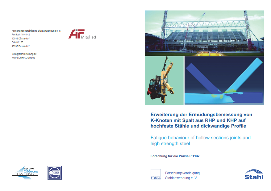
P 1132 – Fatigue behaviour of hollow sections joints and high strength steel
To enable lightweight design, also fatigue loaded structures are more and more made of high strength steels. The K-joint with gap is the favored joint configuration in lattice girder design. Therefore, existing design rules must be extended by larger wall thicknesses and high strength steel grades to facilitate the application and design of such joints. The experimental test program comprehends a total of 55 fatigue tests on K-joints made of rectangular hollow sections (RHS) and circular hollow sections (CHS) of different dimensions made of S355, S500 and S700. Small scale specimens are examined at TNO, Delft on a test frame with single acting load cylinders. Test on large scale specimens are carried out at KIT in Karlsruhe on a specially made rigid test frame.
The evaluation of the experimental investigations is carried out according to the nominal stress concept of EN 1993-1-9 (2010) by the preparation of S-N-curves. In particular, the experiments on small CHS K-joints with over-welded gap show that the fatigue strength depends not only on the joints’ dimensions and the geometric parameters but also on the weld seam design and geometry. This is not considered in the design rules but can be used to build fatigue proof structures. So, for the CHS Kjoints with over-welded gap the fatigue strength can be used by two notch classes from 71 to 90. In contrast, the examined small RHS K-joints are made with weld start and weld end points in the corners of the brace profiles, which makes the weak point of the weld coincide with the geometric hot spot. The test results of these specimens thus represent a lower limit for the fatigue strength. The fatigue strength of K-joints strongly depends on the wall thickness of the chord and the braces and their ratio t. The classification for the nominal stress approach is therefore rightly based on the inverse wall thickness ratio 1 / T = t0 / ti.
The results of the fatigue tests on large RHS and CHS K-joints made of S355 and S700 with 20 mm wall thickness fit well into the existing notch classes and can be classified without reduction due to wall thickness according to CIDECT Design Guide 8 or EN 1993-1-9 (2010). At the same time, numerical calculations are made to extend the scope. The finite element models are calibrated using strain measurements in verification tests. For this purpose, volume elements are used, and the welds are modelled to allow an accurate determination of the local stresses in the weld seam. Parametric studies are carried out to enlarge the investigated dimensional range and to identify the influence of the different geometric parameters, such as the chord slenderness 2Y, thickness ration T, width ratio ß or the brace angle O. For RHS K-joints 72 different joints configurations, each under 4 load configurations have been calculated.
For CHS K-joints 16 joints under 3 different load conditions have been considered, so that a total number of 336 models was analyzed for the parametric study. For the design recommendations by nominal stress approach as well as for the structural stress approach recent research is considered. Beneath that, also SCFs are calculated based on the strain gauge measurements within the tests. Together with the results of the numerical investigations revised SCF formulae are developed. For RHS K-joints, a reevaluation of previous and new data is performed for the load case “Balanced axial Load on the braces” (AX) and appropriate formulas provided with a minor modification of existing CIDECT formulas. For RHS K-joints under ”In-plane bending of the braces” (IPB) no formulas are given in CIDECT. For this a new set of equations has been developed. The evaluation of the structural stresses of CHS K-joints under “Balanced axial loads on the braces (AX) shows, that the SCFs according to CIDECT formulas often provide very conservative values in comparison to the SCFs according to DNV GL-PR-C203 (2016) and FEA. Since DNV GL-PR-C203 (2016) has a wider scope and provides SCF formulas also for the load cases IPB and Out-of-Plane Bending (OPB), it makes sense to use these formulas. Only the formula for SCFs for the chord under IPB is slightly modified, so that all SCFs are on the safe side.
Since the fatigue strength of hollow section joints strongly depends on the dimensionless parameters, this should already be considered in the planning by selecting appropriate parameters. By careful planning and execution, fatigue-proof hollow-section constructions can be realized easily, which is also valid when using high strength steels.
Main content only available in german language.
Published in:
March 2020
Authors:
Dr.-Ing. S. Herion, Dr.-Ing. J. Hrabowski, Prof. Dr.-Ing. T. Ummenhofer, Dipl.-Ing. P. Ladendorf, Dr. ir. R. Pijpers


